Phsical Interface vs Logical Interface
- All the network equipment has a protocol stack from the IP family
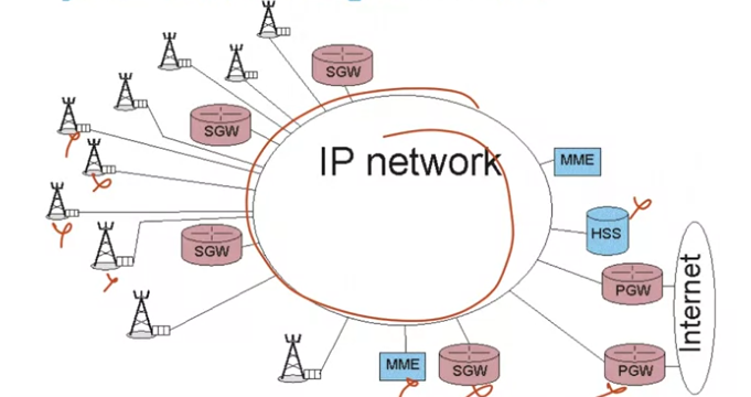
As we’ve said, a 4G network is made up of a set of eNodeBs, a few Serving Gateways, a few MMEs, a few PGW and an HSS. All these nodes are connected to the IP network of the mobile operator.
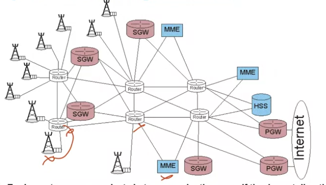
All the equipment of the 4G network have the IP protocol stack and we could say, in plain language, speak IP. The operator’s IP network is made up of a set of interconnected routers.
- equipment can communicate between each other even if they’re not directly physically interconnected by a link: communication via the IP network
The pieces of equipment communicate even if they are not directly linked to each other, from the moment there are routers between them: this is the principle of the IP protocol which is going to take care of retransmission by successive hops.
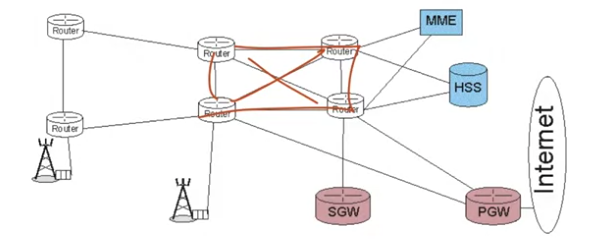
Consequently, we can now define logical interfaces between nodes even they are not physically connected. Let’s first simplify the network and show only the essential elements.
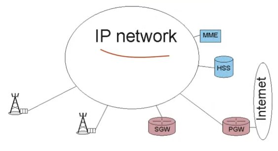
We have here a certain network topology and what we can see is that it’s just an IP network belonging to the mobile operator and the 4G nodes are connected to it.
We’ll define a certain number of interfaces, for example, between two eNodeBs, between an eNodeB and a Serving Gateway and so on. Each interface is specified, because, above the IP, there will be communication protocols specialized in mobility management or the exchange of data taking mobility into account.
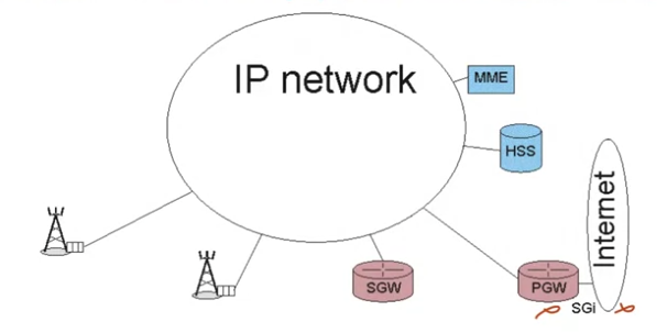
The first interface we see is called the SG-I interface, “I"for Internet. It’s the interface between the P-Gateway and the external IP network that we can interpret as the Internet. Each interface is numbered. I’m using these numbers in the course because those are the ones used by the professionals, but there is no need to remember them.
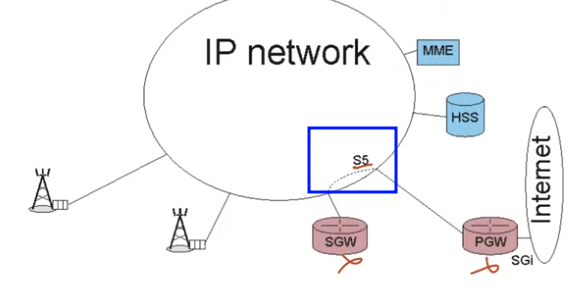
The S5 interface is found between the S‑Gateway and the P-Gateway of the same 4G network. The interface is used to exchange user data and a few signaling messages.
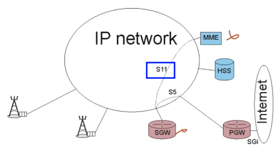
There’s also the interface between the S-Gateway and the MME since the MME is the control equipment and it must also control, for certain functions, the S-Gateway. The S11 interface between the MME and the S-Gateway is only used to exchange signaling.
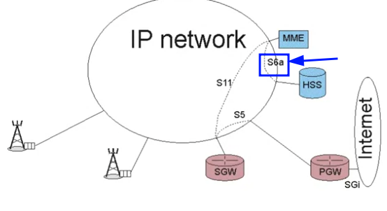
We have the interface between the MME and the HSS called S6a, which also only does signaling.
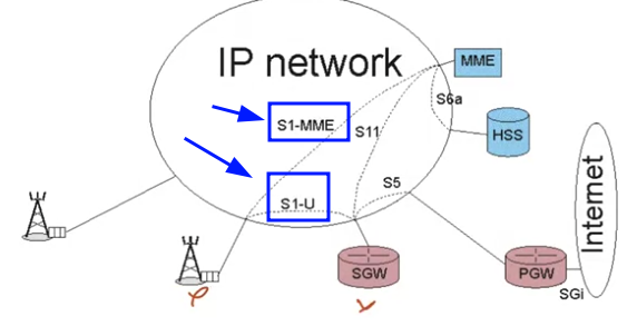
The interface between the eNodeB and the MME called S1-MME, there again, is only for the exchange of signaling. Between the eNodeB and the S-Gateway, we have the S1U interface. Here it’s only for transporting user data, there is no exchange of signaling.
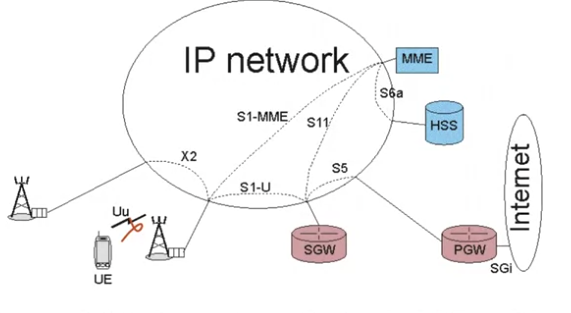
The X2 interface is the one between two eNodeB. Both signaling and user data are transported. Finally, an extremely important interface, the Uu interface: transmission on the radio channel. The UU interface is therefore situated between the terminal (the UE) and the eNodeB. Here again, user data and signaling messages are transported.
Interconnection of Network Cores
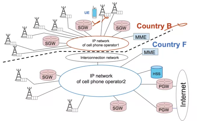
Now let’s look at the interconnection of various mobile networks. This is the principle of international roaming. I am a citizen of country F and I go to country B.
I’ll be taken care of by a local eNodeB, a local S-Gateway, and a local MME. Because we’re staying inside the network, we have the same interfaces that we’ve just seen. That doesn’t change between country B and country F.
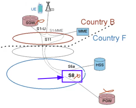
However, in one of the possible implementations, the S-Gateway will communicate with the P‑Gateway of my originating network. Here, it’s an interface that is slightly different from the S5 interface between the S‑Gateway and the P‑Gateway of the same network, the S8 interface is between the S-Gateway and P-Gateway of different networks. For this course, we won’t distinguish between them because that would take us too far into uninteresting technical details and these details are not useful for us to understand the general concepts.
LTE Network Interfaces
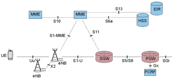
Here’s is a representation of all nodes of a 4G network. There is additional equipment that we won’t be looking at, other than in this video. The EIR, Equipment Identity Register, is the terminal data base for terminals which have been stolen. The interface between the MME and the EIR is called S13.
We also have the PCRF, Policy and Charging Rules Function, which takes care of managing quality of service and there is a Gx interface between the P-Gateway and the PCRF. In this mooc, we will consider the nodes that should be present in every 4G network. We’ll use this representation throughout this course. It summarizes the 4G architecture: the eNodeBs, which cover the territory, the MME and HSS which manage the control function, the SGW and PGW through which the user data is routed.